Small Hardware Description Language
SHDL | Decoder | CompMux | Register
1 Combinational Decoder
1.1 Binary decoder - logic (functional) description
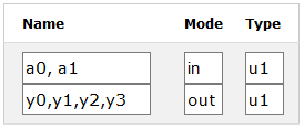
Binary decoder 2-4 has two single bit input signals a0, a1 and four outputs. Each input binary combination sets one output, while the other are 0. Schematic presents decoder circuit made with the logic gates.
 |
 |
 |
Signals with the same mode and data type can be declared in the same cell in the model ports and signals table. The logic circuit schematic is described with assignment statements and Boolean operators: bindec1
y3 = a0 and a1
y2 = not a0 and a1
y1 = a0 and not a1
y0 = not a0 and not a1
1.2 Binary decoder - behavioral description
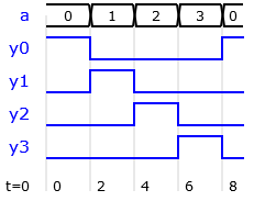
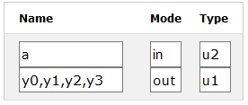
The same decoder can be described in a high-level model. This time the input is declared as 2-bit unsigned vector, whith the possible values "00","01","10" or "11" in binary or 0,1,2 and 3 in decimal notation. The output y0 is 1 at the input value 0, y1 is 1 at the input 1, y2 is 1 at the input 2 and y3 at 3:
Conditional if statements are used to test input values and set outputs:
if a=0 then y0=1; y1=0; y2=0; y3=0 end
if a=1 then y0=0; y1=1; y2=0; y3=0 end
if a=2 then y0=0; y1=0; y2=1; y3=0 end
if a=3 then y0=0; y1=0; y2=0; y3=1 end
Parsing the presented code creates a latch warning: the latch is synthesized to hold output values, if the conditions do not cover all the combinations. One solution is to define default output values before conditional statements. In this case, only one assignment is required in each if statement: bindec2
y0=0; y1=0; y2=0; y3=0;
if a=0 then y0=1 end
if a=1 then y1=1 end
if a=2 then y2=1 end
if a=3 then y3=1 end
A sequence of conditions is better described with an if-elsif statement. In this case, the last condition (a=3) can be replaced with an else statement:
y0=0; y1=0; y2=0; y3=0;
if a=0 then y0=1
elsif a=1 then y1=1
elsif a=2 then y2=1
else y3=1 end
The VHDL code generator will translate this if-elsif-else to a case statement, because the conditions are testing the values of a single vector signal. Also the output can be declared as vector and an assignment of the default output values is not required any more: bindec2a
if a=0 then y="0001"
elsif a=1 then y="0010"
elsif a=2 then y="0100"
else y="1000"
1.3 Binary decoder - combinational table
Combinational logic can be described with a truth table. The circuit model is then based on the table (vector array) declaration and a logic describing reading the array. The table is implemented as read-only memory (ROM) or look-up table (LUT) in FPGA.
The array data is described in SHDL with internal signals specified by number and type of elements. For example, data type: 4u8 describes an array or four 8-bit vectors. The ROM table elements shoud be initialized at the declaration.
Description of a binary decoder using table: bindec3
entity bindec3
a: in u2;
y: out u4;
table: 4u4 = "0001","0010","0100","1000";
begin
y = table(a)
end
1.4 Binary decoder - expression
Some circuits can be best described with mathematical expressions. Binary decoder output can be computed by shifting a constant "0001" for a specified number of bits to the left. The input vector presents the corresponding number: bindec4
entity bindec4
a: in u2;
y: out u4;
c: u4 = "0001";
begin
y = c sll a
end
1.5 Priority encoder
A priority encoder output index of the input which is set to one. If more than one of the inputs are set, the encoder selects the input with the highest index. Input signals with higher index have priority over the inputs with lower indices.
The output value 0 could mean two conditions: input with the index 0 is set, or no inputs are set. The encoder can have additional output (v, valid) which is set only if at least one of the inputs are set.
- d3 d2 d1 d0 = 1000, y = 3, v = 1
- d3 d2 d1 d0 = 1010, y = 3, v = 1 -- d3 has priority over d1
- d3 d2 d1 d0 = 0111, y = 2, v = 1 -- d2 has priority over d1 and d0
- d3 d2 d1 d0 = 0011, y = 1, v = 1 -- d2 has priority over d0
- d3 d2 d1 d0 = 0001, y = 0, v = 1 -- d0 is active
- d3 d2 d1 d0 = 0000, y = 0, v = 0 -- no inputs are active
The input priority is set by the order of HDL if statements. An example of 4-input priority encoder: priority
if d(3)=1 then y=3; v=1
elsif d(2)=1 then y=2; v=1
elsif d(1)=1 then y=1; v=1
elsif d(0)=1 then y=0; v=1
else y=0; v=0
end
Excercises
- Try to model the binary decoder with a sequence of if statements and with one if-elsif-else statement. Observe the difference in generated VHDL code.
- Is the order of the conditions important is this circuit?
Is it OK to move the statement for setting the output default value to the end of the code? - Design a demultiplexer which is a binary decoder with an enable input. When the enable is 1, the circuit operates as the binary decoder. When the enable is 0, all the outputs are 0.
- Design a model of an encoder with the opposite function of the binary decoder.
Boolean model: d = (y(2) or y(3)) & (y(1) or y(3)) - Design a thermometer encoding circuit. A value on the input vector defines
the number of ones at the output:
y=000 at 0, 001 at 1, 011 at 2 and 111 at 3.