Laboratory for Integrated Circuit Design: Red Pitaya Projects
The Laboratory for Integrated Circuit Design is using programmable logic devices from Xilinx since 1995. We developed several boards based on Xilinx FPGA devices and used them for educational purpose. The students are able to quickly prototype and test their digital design projects on our development and emulation systems.
Programmable Systems-on-Chip provide more resources for prototyping hardware and software development. The Red Pitaya STEMlab board adds powerful analog I/O and nice sample designs, so we use it extensively for the laboratory work and student projects.
Development tools
Vivado
Vivado is a Xilinx hardware development tool for FPGA and SoC devices. Vivado - HLx can be can be downloaded from: www.xilinx.com/support/download.html. The download site requires a free registration. Recommended installation is with Vivado HLx Web Installer, select an install option HLx WebPACK (this one has free license) and SoCs, Zynq-7000 Devices. The tool requires approx. 30 GB hard drive.
Tutorial projects
Demo project 2024
Based on the updated v094 project (FPGA sub-projects), we have prepared a demo project for Vivado 2023.1. Project archive: redpitaya-v094-demo-Vivado23.xpr.zip
The demo project was tested on STEMlab 125-14 with Red Pitaya OS 2.0. After generating bitstream, execute in Vivado Tcl Console: exec bootgen -image rp.bif -arch zynq -process_bitstream bin -w
and transfer the bin file located in redpitaya.runs/impl_1/red_pitaya_top.bit.bin to the board.
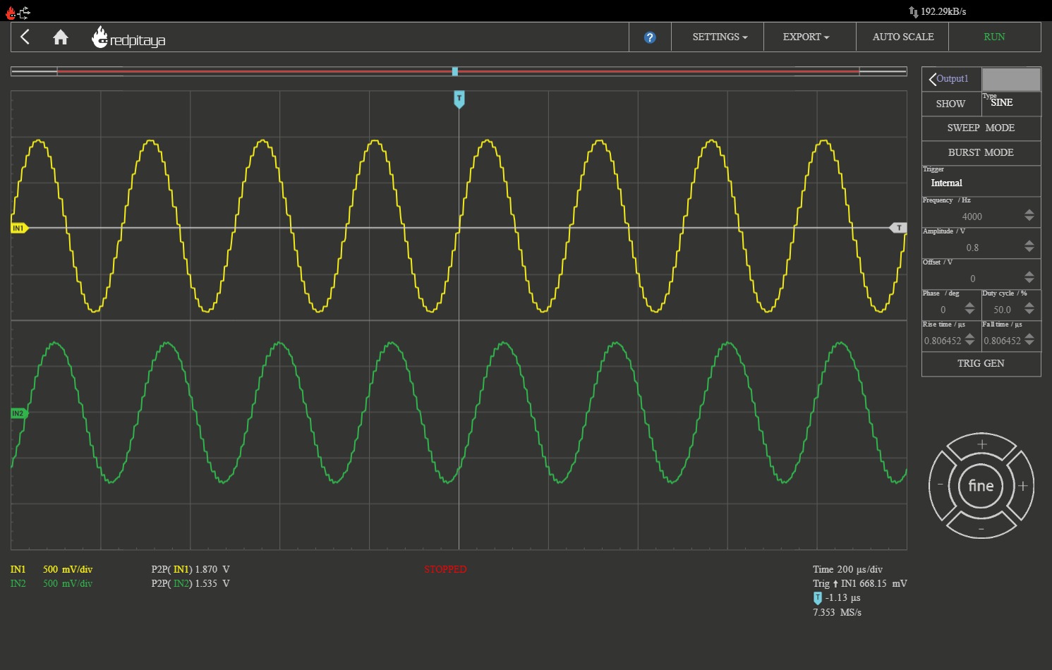
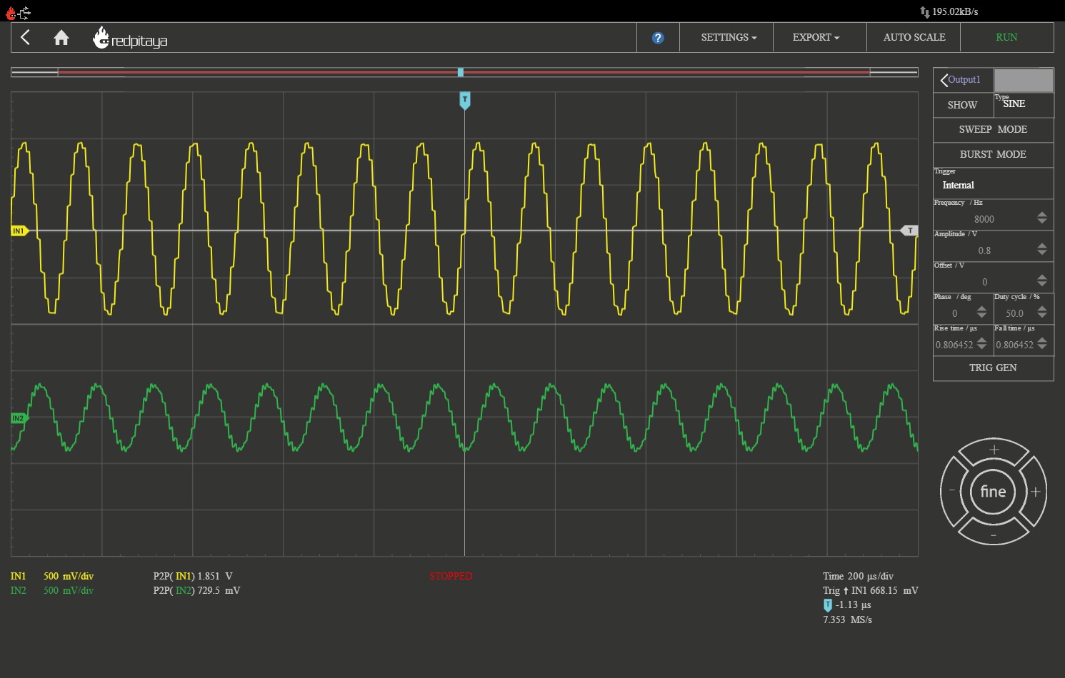
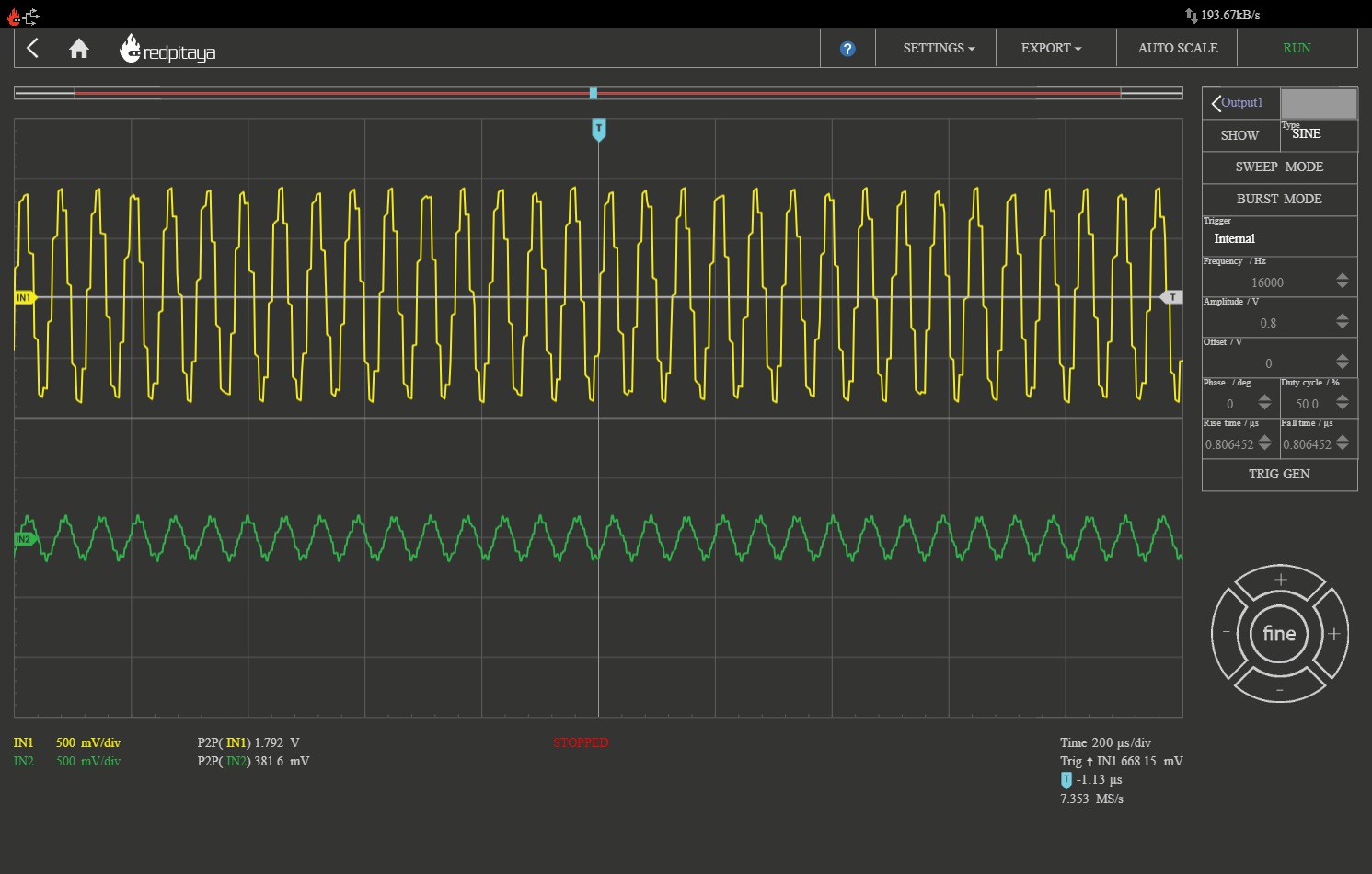
Use script set_fpga.sh to connect the bin file with the Oscolloscope application. Check some scope images: sin1k.jpg,
sin4k.jpg, sin8k.jpg,
sin16k.jpg.
Detailed description coming soon!
Red Pitaya - classic project
Instructions for compiling classic project in Vivado 2019 with FPGA description in SystemVerilog. The classic project includes logic modules for digital oscilloscope, arbitrary signal generator and PID regulator and can be extended with your customized instrumentation logic.
Red Pitaya - v0.94
Instructions for compiling the lastet project in Vivado 2020 with FPGA description in SystemVerilog. The project includes logic modules for digital oscilloscope, arbitrary signal generator and a custom signal processing component.
Signal processing
Instructions for replacing PID with a custom signal processing component in VHDL.
1. Scaling & averaging
2. Numerical oscillator
3. Data sampling
Student projects
Jaka Koren: Red Pitaya VGA tutorial
In this tutorial I will explain how to display a picture on a monitor using Red Pitaya. I used Xilinx Vivado 2016.4 for hardware programming with Xilinx SDK 2016.4 for software application. The picture is just a simple matrix with "1" and "0" that represent black and white pixels. Picture can be scalled, moved and it can display different patterns.
The next tutorial presents a simple VGA game: Ping Pong. The game is using our Red Pitaya VGA extension board with VGA output, controller buttons and rotary encoder.
 video (in Slovene)
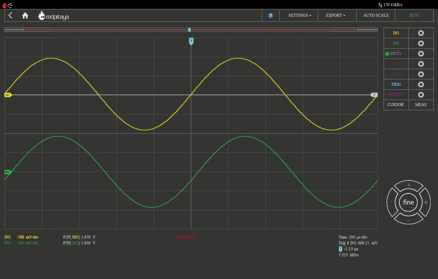