[LNIV Red Pitaya](index.html)
# [Red Pitaya](https://www.redpitaya.com/) Project 0.94
Red Pitaya STEMlab is a programmable instrumentation platform based on Xilinx Zynq SoC. The programmable logic modules are
designed in a hardware description language SystemVerilog and available on [GitHub](https://github.com/RedPitaya/RedPitaya).
The project is a good starting point for development of custom signal processing modules.
It includes peripheral modules for digital oscilloscope, arbitrary signal generator and PID regulator. The main component
connects a processing system (red_pitaya_ps) with the peripheral modules, as presented in a simplified block diagram:
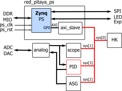
The peripheral modules are connected on the processor general purpose AXI bus which is translated to simple
system bus (sys). The table presents address space assigned to specific modules:
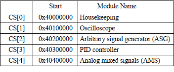
A Housekeeping module (red_pitaya_id.v) contains identification register and some basic control registers, for example
Digital Loopback is at the address ```0x40 000 00C```.
The complete register list is described in [Redpitaya Developer Guide](https://redpitaya.readthedocs.io/en/latest/developerGuide/software/build/fpga/regset_common.html).
In the proposed project, we replaced the rarely used module PID, which is connected to both input and output analog channels,
by the custom component.
The component **proc** is connected to ADC or signal generator input channels and DAC output channels. The processing
system controls the component through a simple system bus (sys[3]).

A digital_loop control signal from the housekeeping component is used to control signal path of the component **proc**. Setting digital_loop to 1 connects its inputs (dat_a_i, dat_b_i) to ASG and outputs (dat_a_o, dat_b_o) to
the scope component. The **proc** outputs are also connected to external DAC.
## Vivado 2020 project
We prepared a ZIP archive with the classic project source files and build scripts for Vivado 2020.1.
- Unzip the archive: [redpitaya94.zip](redpitaya94.zip)
into your project folder. The SystemVerilog source files are located in rtl subfolder.
- Run Xilinx Vivado, navigate to the project folder using TCL console and run the script:
```
cd c:/proj/redpitaja
source ./make_project.tcl
```
- The script creates a new Vivado project, block design and includes source files. Open the source red_pitaya_top.sv and check
the code. The Vivado project file is located inside project folder.
- Start Vivado compilation (Run Implementation, Generate Bitstream) and locate the output file
red_pitaya_top.bit in a folder project\redpitaya.runs\impl_1.
## Upload to STEMlab
- Connect STEMlab to local internet router and use SFTP tool (for example [Bitvise SSH Client](https://www.bitvise.com/ssh-client) to upload the bitstream file in the board local folder (root).
- Change the ScopeGen application setting to use this file by writing the path to the bitstream in:
```/opt/redpitaya/www/apps/scopegenpro/fpga.conf```).
- Open Red Pitaya in your web browser and run Oscilloscope. Set one signal generator output by clicking on the wheel near
OUT1 and selecting ON. The scope will show a sine wave. Now you can test digial loopback by writing in a terminal:
```
monitor 0x4000000c 1
```