[LNIV Red Pitaya](index.html)
# [Red Pitaya](https://www.redpitaya.com/) Classic Project
Red Pitaya STEMlab is a programmable instrumentation platform based on Xilinx Zynq SoC. The programmable logic modules are
designed in a hardware description language SystemVerilog and available on [GitHub](https://github.com/RedPitaya/RedPitaya).
The project Classic project is a good starting point for development of custom signal processing modules.
It includes peripheral modules for digital oscilloscope, arbitrary signal generator and PID regulator. The main component [red_pitaya_top.sv](https://github.com/RedPitaya/RedPitaya/blob/master/fpga/prj/classic/rtl/red_pitaya_top.sv)
connects a processing system (red_pitaya_ps) with the peripheral modules, as presented in a simplified block diagram:
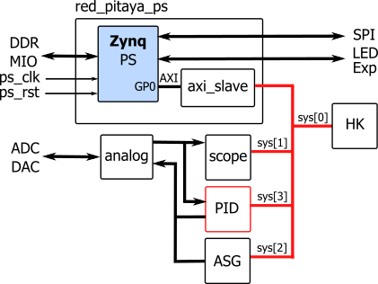
The peripheral modules are connected on the processor general purpose AXI bus which is translated to simple
system bus (sys). The table presents address space assigned to specific modules:
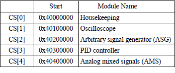
A Housekeeping module (red_pitaya_id.v) contains identification register and some basic control registers, for example
Digital Loopback is at the address ```0x40 000 00C```.
The complete register list is described in [Redpitaya Developer Guide](https://redpitaya.readthedocs.io/en/latest/developerGuide/fpga.html).
If you plan to add your module which requires access to high-speed analog inputs and/or outputs, we suggest to replace
the module PID with a custom circuit. The development tool Vivado supports mixed language projects and your circuit can
be described in Verilog, SystemVerilog or VHDL.
## Vivado 2019 project
We prepared a ZIP archive with the classic project source files and build scripts for Vivado 2019.
- Unzip the archive: [redpitaya-classic.zip](https://lniv.fe.uni-lj.si/courses/div/redpitaya-classic.zip)
into your project folder. The SystemVerilog source files are located in rtl subfolder.
- Run Xilinx Vivado, navigate to the project folder using TCL console and run the script:
```
cd c:/proj/redpitaja
source ./make_project.tcl
```
- The script creates a new Vivado project, block design and includes source files. Open the source red_pitaya_top.sv and check
the code. The Vivado project file is located inside project folder.
- Start Vivado compilation (Run Implementation, Generate Bitstream) and locate the output file
red_pitaya_top.bit in a folder project\redpitaya.runs\impl_1.
## Upload to STEMlab
- Connect STEMlab to local internet router and use SFTP tool (for example [Bitvise SSH Client](https://www.bitvise.com/ssh-client) to upload the bitstream file in the board local folder (root).
- Change the ScopeGen application setting to use this file by writing the path to the bitstream in:
```/opt/redpitaya/www/apps/scopegenpro/fpga.conf```).
- Open Red Pitaya in your web browser and run Oscilloscope. Set one signal generator output by clicking on the wheel near
OUT1 and selecting ON. The scope will show a sine wave. Now you can test digial loopback by writing in a terminal:
```
monitor 0x4000000c 1
```
- If you implemented your custom circuit replacing PID module, you can access the circuit registers at the addresses starting
at ```0x40300000```.

## Application in C
The software application for setting and reading the circuit registers can be written in C. You can use gcc compiler in
Red Pitaya terminal or Vivado SDK with cross compiler (setting OS Platform: Linux). The gcc can be executed in the terminal
with:
```
gcc -o app app.c
./app
```
Here is an example of an application setting Digital Loopback to 1:
```C
#include <stdio.h>
#include <stdint.h>
#include <unistd.h>
#include <sys/mman.h>
#include <fcntl.h>
#include <stdlib.h>
void Out32(void *adr, int offset, int value)
{
*((uint32_t *)(adr+offset)) = value;
}
int In32(void *adr, int offset)
{
return *((uint32_t *)(adr+offset));
}
int main(int argc, char **argv)
{
int fd;
int BASE = 0x40000000; // Housekeeping base address;
void *adr;
char *name = "/dev/mem";
/* open memory device */
if((fd = open(name, O_RDWR)) < 0) {
perror("open");
return 1;
}
/* map the memory, start from BASE address, size: _SC_PAGESIZE = 4k */
adr = mmap(NULL, sysconf(_SC_PAGESIZE), PROT_READ|PROT_WRITE, MAP_SHARED, fd, BASE);
printf("Loop back is: %d\n", In32(adr, 0x0c));
/* write to loop back register */
Out32(adr, 0x0c, 1);
printf("Loop back set to: %d\n", In32(adr, 0x0c));
munmap(adr, sysconf(_SC_PAGESIZE));
return 0;
}
```