# Red Pitaya VGA tutorial
Jaka Koren, Faculty of Electrical Engineering, Ljubljana
### About
In this tutorial I will explain how to display a picture on a monitor using Red Pitaya. I used Xilinx Vivado 2016.4 for hardware programming with Xilinx SDK 2016.4 for software application. The picture is just a simple matrix with "1" and "0" that represent black and white pixels. Picture can be scalled, moved and it can display different patterns.
### Required software
* Xilinx Vivado 2016.4
* SDK 2016.4
Both can be installed from official Xilinx webside for free.
### Required hardware
* Red pitaya
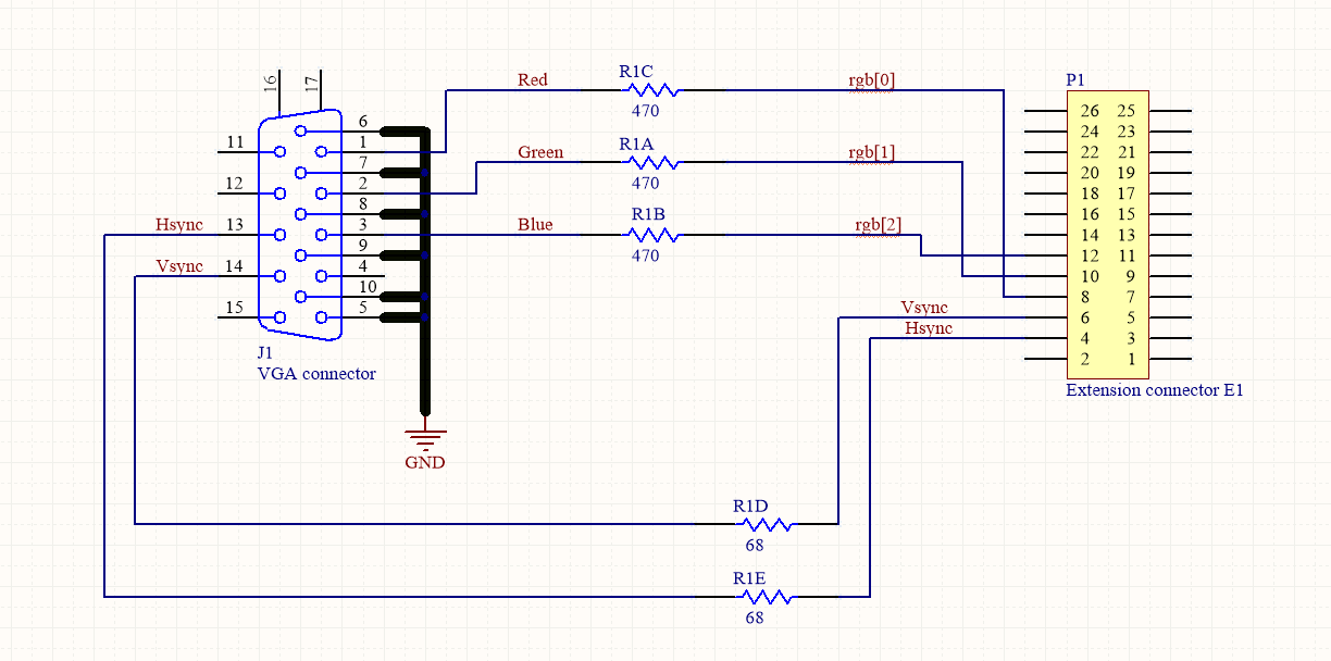
* Hardware extension for VGA connector
### Step by step tutorial
Open vivado and choose **create new project**, type in project name and project location. It is recommended to choose location that has no spaces in the file path, because vivado can have some problems with it.
Click next till you come to the page when you have to define what hardware you are using.
Select **"Boards"** and choose Red Pitaya.
>Vivado doesn't have Red Pitaya installed by default so you have to copy board definitions from
[redpitaya-board.zip](./jkoren/redpitaya-board.zip) to C:\Xilinx\Vivado\2016.4\data\boards\board_files\
We will use **Block design** to design our project, because it is more managable, but we will still have to write some VHDL code, because not all the IPs we will be using are already implemented in Vivado.
We will start by writing code in VHDL and creating our custom made IPs.
First we need to define resolution and frequency for the monitor. Below is a table with values chosen for resolution 800 x 600, with frequency 50 MHz.
|VGA 800 x 600 |Number of periods|number of rows|
|------------- |---------------- |------------- |
|period |H = 1040 |V = 666 |
|visible section|Hp = 800 |Vp = 600 |
|pulse start |Hf = 856 |Vf = 637 |
|pulse duration|Hs = 120 |Vs = 6 |
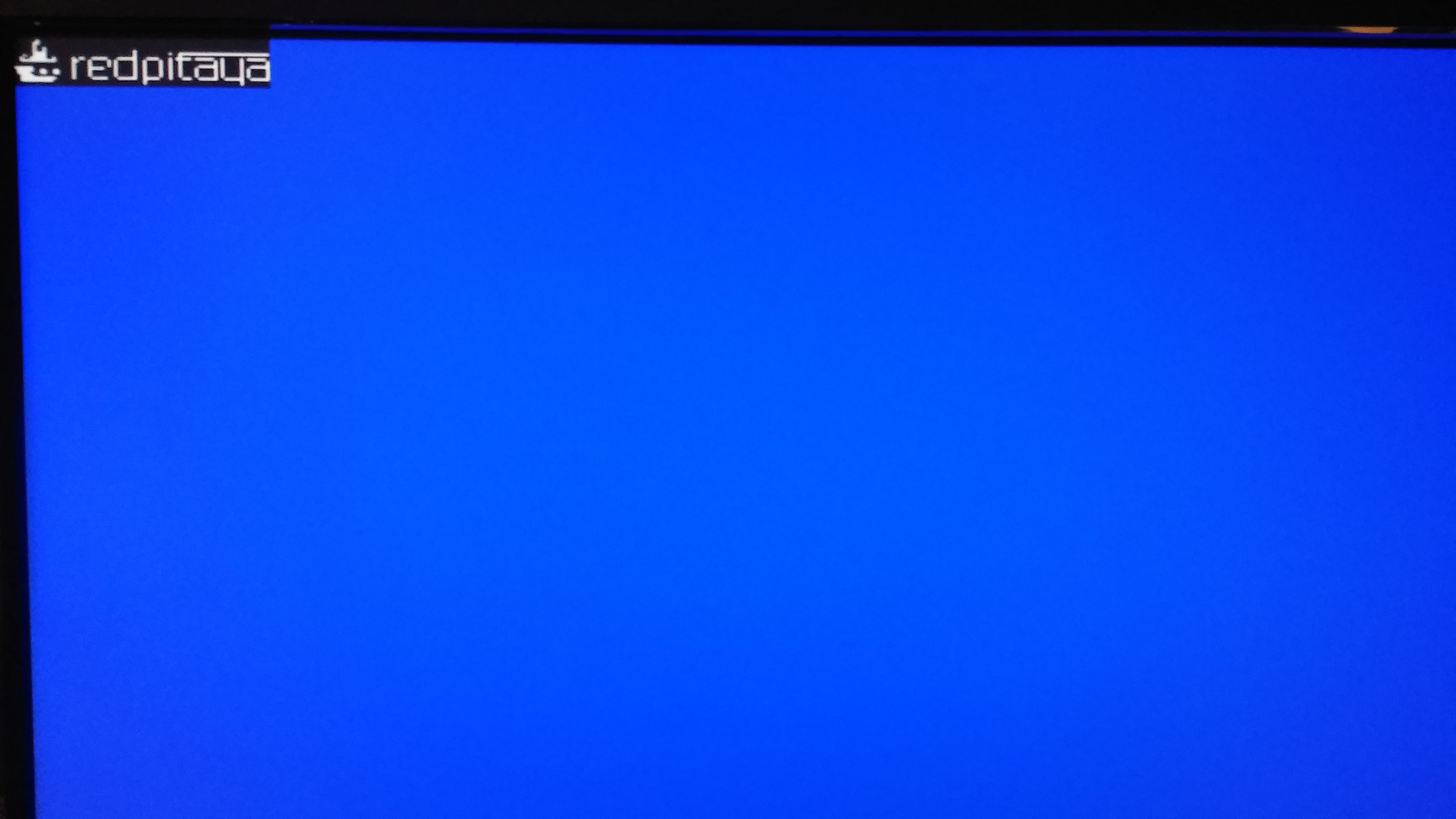
Because this was my first project I wanted to start slowly. First I wrote a simple code and simulated it. I filled an array with "1" and "0". Once the simulation worked fine, I tried to display it on the screen. It is a simple Red Pitaya logo. By changing the position of "1" and "0", you alter the picture.
```vhdl
type logo is array(0 to 19) of std_logic_vector(0 to 79);
signal slika: logo := (
"00000000000000000000000000000000000000000000000000000000000000000000000000000000",
"00000000100000000000000000000000000000000000000000000000000000000000000000000000",
"00000001100000000000000000000000000000000000000000000000000000000000000000000000",
"00000001000000000000000000000000000000000000000000000000000000000000000000000000",
"00000001001000000000000000000000000000000000000000000000000000000000000000000000",
"00000001001000000000000000000000000000100000000000000000000000000000000000000000",
"00000001111000000000000000000000000000100000000001001111111111111111111111111111",
"00001001111000000000000000000000000000100000000000001000000000000000000000000000",
"00010011111001000001011001111100011111100011110001011111011111100100000101111110",
"00011111111111000001100010000010100000100100001001001000000000010100000100000001",
"00000000000000000001000010000010100000100100001001001000000000010100000100000001",
"00000000000000000001000010000010100000100100001001001000001111110100000100111111",
"01111110000000000001000011111000100000100100001001001000010000010100000101000001",
"00111110011001100001000010000000100000100100001001001000010000010100000101000001",
"00111100011001100001000010000000100000100100001001001000010000010100000101000001",
"00011110000000000001000010000000100000100100001001001000010000010100000101000001",
"00011111111111000001000001111100011111100111110001000111001111110011111100111111",
"00011111111110000000000000000000000000000100000000000000000000000000000100000000",
"00000000000000000000000000000000000000000100000000000000000000000000000100000000",
"00000000000000000000000000000000000000000000000000000000000000000000000000000000");
```
For displaying the picture we need a process that runs line by line on the screen. Below is the process that shifts the cursor on the screen, with frequency 50 MHz.
```vhdl
P1: process (clk50)
begin
if rising_edge(clk50) then
clk_div <= not(clk_div);
if hst_sig < (H-1) then
hst_sig <= hst_sig +1;
else
hst_sig <= (others => '0');
if vst_sig < V-1 then
vst_sig <= vst_sig +1;
else
vst_sig <= (others => '0');
end if;
end if;
end if;
end process;
```
A second process to read the data from the array.
```vhdl
P2: process (hst_sig, vst_sig, cx_sig, cy_sig)
begin
if (hst_sig < Hp) and (vst_sig < Vp) then -- and en = '1' then
if(cx_sig < Hslika) and (cy_sig < Vslika) then
if slika(to_integer(cy_sig))( to_integer(cx_sig)) = '1' then
rgb <= "111";
else
rgb <= "000";
end if;
else
rgb <= "001";
end if;
else
rgb <= "000";
end if;
end process;
```
For the monitor to work correctly, it is necessary to send syncronization pulses at the exact time, for the exact duration.
```vhdl
--signals to synhronize the screen
hsync <= '1' when hst_sig >= Hf and hst_sig < Hf + Hs else '0';
vsync <= '1' when vst_sig >= Vf and vst_sig < Vf + Vs else '0';
rgb_out <= rgb_in;
end Behavioral;
```
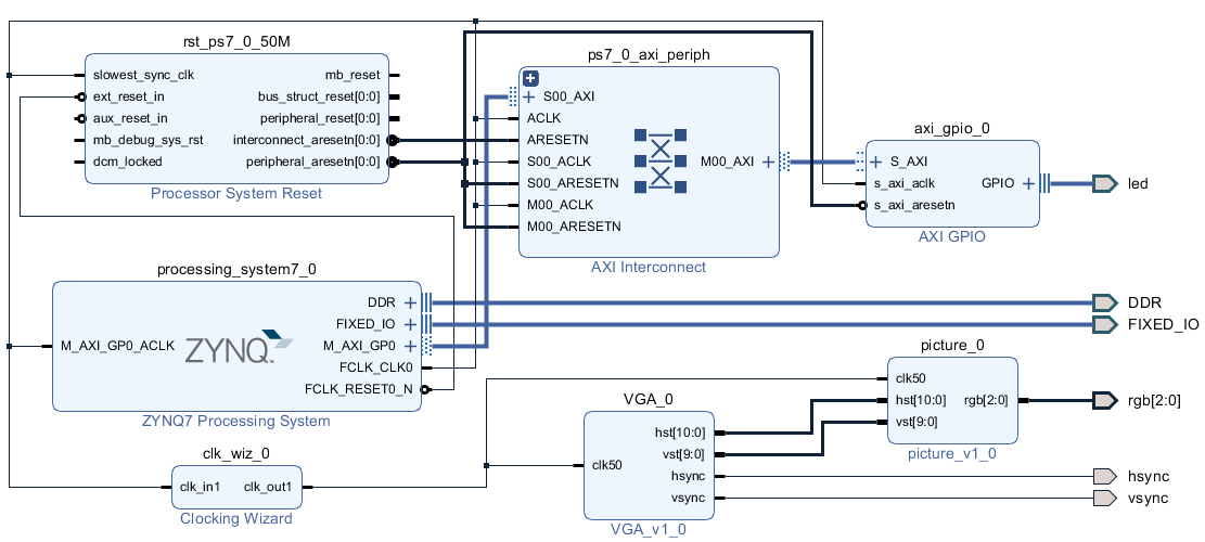
I packed this two codes in sapareted IP, and created a simple block diagram.
Below is the result.
After this was working fine, I wanted to be able to change picture pattern, picture size and location on the screen.
I added a few more ports which will be later controlled through AXI_GPIO, with SDK application.
```vhdl
entity picture is
Port (
clk50: in STD_LOGIC;
data_position: in unsigned(16 downto 0);
Offset: in unsigned(15 downto 0);
size: in unsigned(15 downto 0);
data_in: in STD_LOGIC;
hst: out unsigned(10 downto 0);
vst: out unsigned(9 downto 0);
rgb: out STD_LOGIC_VECTOR(2 downto 0));
end picture;
```
* **clk50** - 50 MHz clock
* **data_position** - position to write the data + Write enable bit
* **Offset** - picture location on the screen
* **size** - picture size
* **data_in** - "1" or "0" that are written in array
* **hst, vst** - current position on the screen
* **rgb** - signal to be displayed on the screen
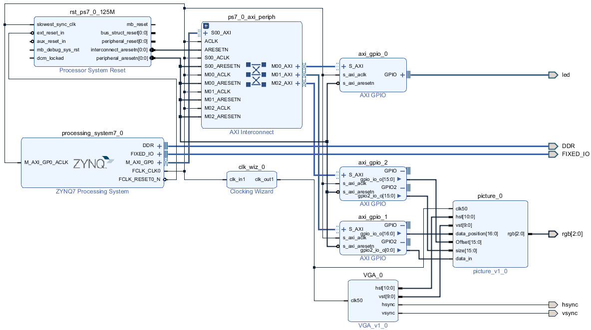
I created another block design and connect it as is seen on the picture.
##### Block diagram explaned
If you are doing your block design for the first time, I reccomend the _Zynq book_ as a good starting point, because it explains basic step how to build a project in vivado.
Ok, let's explain block diagram:
1. First we start with Zynq7 processing system, this are the brains.
2. I added three AXI_GPIO blocks
- The first one is connected to on board leds, and it is there just to check if the programm is running
- The second one has two outputs, first one is controlling where and when we write our data to array, on second, the actual data is comming in.
- The third one also has two outputs, the first one controls the position on the screen the second one picture size.
3. pictureIP is used to save picture, and to read from the array
4. VGAIP is used to set signals to synhronize the screen and output the data.
5. there is another IP, Clocking Wizard. Linux sets the clock on FCLK_CLK0 port to 125 MHz, and because we need 50 MHz, we place Clocking Wizard to lower the clock frequency to desired rate.
>picture IP and VGA IP are included in this tutorial: [IPVP.zip](./jkoren/IPVP.zip). Unzip them in the project folder and import them in the project using TCL command
```TCL
set_property ip_repo_paths <path_project_file> [current_project]
update_ip_catalog
```
##### Setting 50 MHz clock
First we need to set source clock from the ZYNQ7 IP. This can be made by double clicking on the ip and there manually set the clock to 125 MHz, but there is also TCL command to do the same.
```TCL
set_property -dict [list CONFIG.PCW_FPGA0_PERIPHERAL_FREQMHZ {125.00000}] [get_bd_cells processing_system7_0]
```
After setting 125 MHz clock we have to devide it to 50 MHz that is used in our case. For this we use Clocking Wizard, again the setting can be set manually by double clicking on it, or just by writing this command in TCL:
```TCL
set_property -dict [list CONFIG.PRIMITIVE {PLL} CONFIG.PRIM_SOURCE {Global_buffer} CONFIG.CLKOUT1_REQUESTED_OUT_FREQ {50.000} CONFIG.USE_LOCKED {false} CONFIG.USE_RESET {false} CONFIG.CLKOUT1_DRIVES {BUFG}] [get_bd_cells clk_wiz_0]
```
After generating bitstream we can fokus on writing an application in SDK.
1. **File** -> **export** -> **export hardware**
2. **File** -> **Launch SDK**
For programming on Red Pitaya we have to choose **file** -> **new** -> **application project**, then you select linux as your OS Platform.
For SDK to recognize the libraries, we need to show the path where they are saved.
1. Right click on the project
2. Properties
3. C/C++ Build -> Paths and symbols
4. Includes -> here we have to add path to where all the libraries are saved.
>I had quite a few problems with libraries, but this worked for me, and I hope it is a general solution.
Picture below shows the path where the libraries are saved in sdk instalation folder.
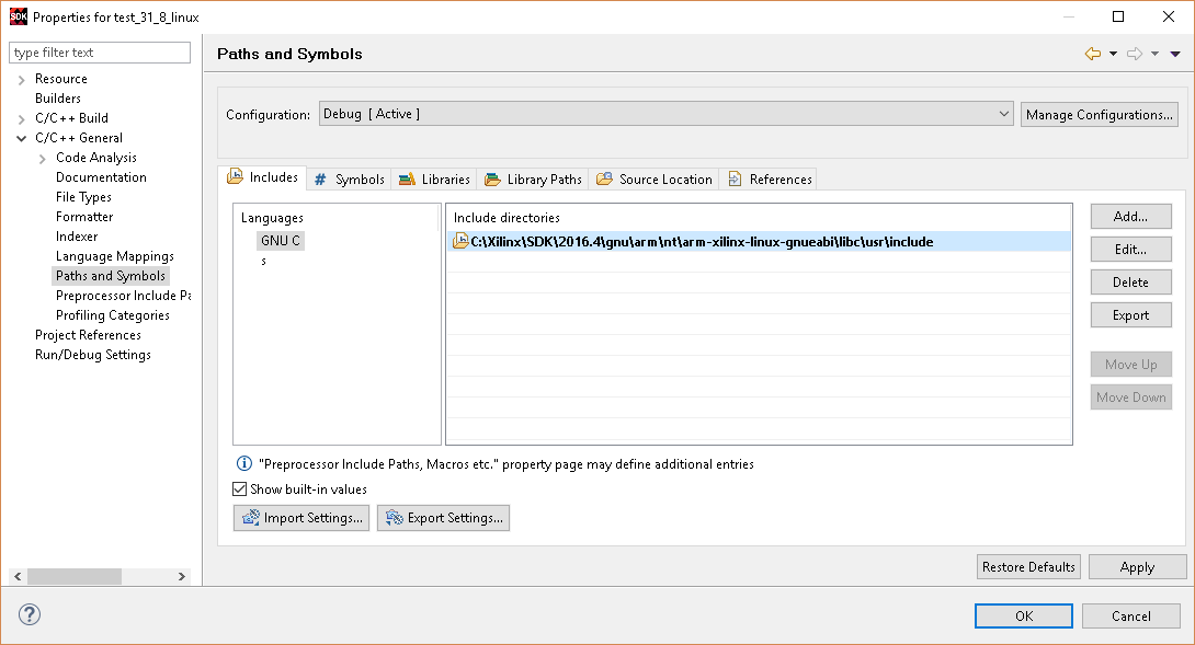
Once we define all the libraries we can start to write our program.
Every AXI_GPIO has its own address, where we can set values on the output. This address can be seen in vivado address editor above the block diagram. There is written just the first address of the AXI_GPIO, other addresses can be seen in AXI_GPIO datasheet.
##### SDK code explaned
For every AXI_GPIO we have to define its address and its size as is shown below
```c
#define MAP_SIZE 4096UL
#define MAP_MASK (MAP_SIZE - 1)
unsigned long addr = 0x41200000;
```
This is how we define dual port. Second port is shifted by 0x0008.
```c
virt_addr_2_1 = map_base_2 + (addr_2 & MAP_MASK_2);
virt_addr_2_2 = map_base_2 + ((addr_2 + 0x0008) & MAP_MASK_2);
```
SDK application: [RVGA_APP_SDK.c](./jkoren/RVGA_APP_SDK.c)
Final picture on the screen is shown below.

##### How to run an application on Red Pitaya
For running the program on Red Pitaya I used Winscp, to transfer _.bit_ file from vivado and _.elf_ file from SDK on the board.
Then open Putty, and run the application.
Go to folder where you saved files on Red Pitaya and type:
1. cat <file_name.bit> >/dev/xdevcfg
2. chmod +x <file_name.elf>
3. ./ <file_name.elf>
Below are some useful links:
1. Red pitaya official site: https://redpitaya.com/
2. The Zynq Book: http://www.zynqbook.com/
3. Osnove programa Vivado: http://lniv.fe.uni-lj.si/xilinx/vivado.htm (Slovenian)