This tutorial is an upgrade of the first lesson “Display picture with VGA”, where the basics about how to start working with Red Pitaya are covered. It is a step by step guide on how to make a simple game on Red Pitaya board. I choose the PING PONG game, but with little modification, it can be changed to something else.
Game is designed for two players. Score is displayed on the top of the screen. The player that reaches 11 points first, wins the game and the score bar is cleared.
Different colors, ball speed and size, and size of the tables can be easily set, so the players can modify game appearance and difficulty according to their wishes.
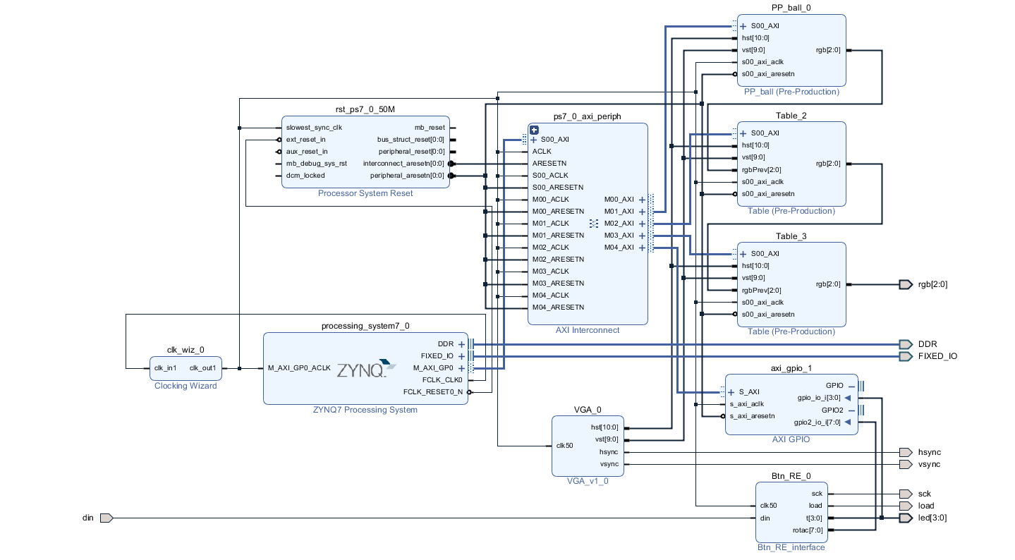
Components on block diagram for:
VGA IP sends the coordinates to PP_ball, Table and Table IP. Each of those three generates their part of the picture. PP_ball is the first in the row, and it draws the ball and score bar. Two Table IPs add the first and the second racket. They are in a series connection, and the last component sends the united RGB signal to the screen.
Btn_RE IP is there for capturing the signals from the buttons and rotary encoder from the extern board.
To connect SDK application and hardware designed in Vivado there needs to be some registers reserved through which the data can be send and received from. There are two ways to do this. The first one is general purpose interface, AXI_GPIO. Two disadvantages of this solution are, that it uses a lot of resources, and that it only has two ports. Although it is a fast and simple solution, I would need to use a lot of them to communicate with all my ports. The second way is packing our code as AXI peripheral, where we can decide how many register we are going to use.
Adresses can be seen in address editor above block diagram. The first address is written and others are shifted by 4, because 32 bits width data bus are used.
To make the AXI peripheral IP, write you code in vhdl, then select AXI peripheral when you want to package your IP.
Axi peripheral has two components. The first component is the one where registers are defined, the second one contains our code. To access our component, I included my code in the project and connected components with port map. Data bus width is set to 32 bit, but because not all bits are needed, I had to match the signal vector length with the number of bits that I am reading from the registers.
reg0 <= unsigned(slv_reg0(12 downto 0));
reg1 <= unsigned(slv_reg1(19 downto 0));
reg2 <= unsigned(slv_reg2(11 downto 0));
reg3 <= slv_reg3(2 downto 0);
reg4 <= slv_reg4(2 downto 0);
This component has 3 inputs for tracking current cursor position on the screen, which are also visible on the block diagram. Additional 5 inputs, that aren’t directly seen on the block diagram are connected to the registers. These are registers for communicating with SDK application. As I already mentioned each of the registers has its unique address and has to be initialized in the SDK.
Hardware inputs:
clk50: in STD_LOGIC;
hst: in unsigned(10 downto 0);
vst: in unsigned(9 downto 0);
rgbPrev: in std_logic_vector(2 downto 0);
rgb: out STD_LOGIC_VECTOR(2 downto 0));
Software inputs:
data_position: in unsigned(12 downto 0);
offset: in unsigned(19 downto 0);
size: in unsigned(11 downto 0);
data_in: in STD_LOGIC_VECTOR(2 downto 0);
background: in std_logic_vector(2 downto 0);
First I created an array, for saving my data. I choose array dimensions 16 * 256, with 3 bits for color data, so 8 different colors can be set.
-- 16*256 rectangle
type logo is array(0 to 4095) of std_logic_vector(2 downto 0);
signal picture_array: logo;
Array mustn’t be read from and written to at the same time, so I set the flag, to enable writing in it.
if  wen = '1' then
    picture_array(to_integer(data_position(12 downto 1))) <= data_in;
 end if;
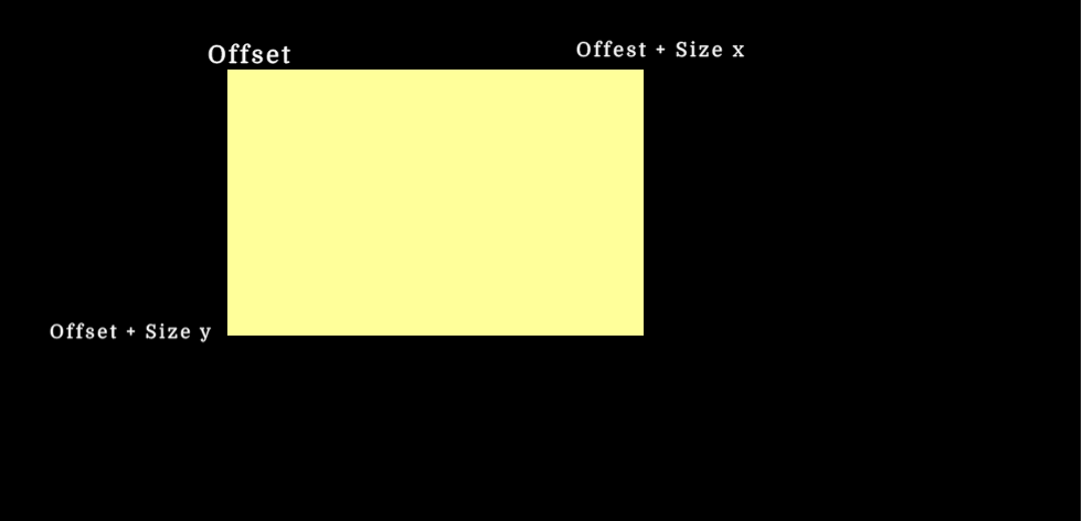
Below is the code that enables reading from the array. We have to remember that our array is smaller then the screen size, so we have to calculate, when our cursor is in the right position. I set picture start position (XOff, YOff), and the picture size (Hp_Size, Vp_Size).
   if ((hst_sig >= resize(Xoff, 11)) and (hst_sig < (resize(Hp_size,11) + resize(Xoff, 11)))) and ((vst_sig >= resize(Yoff,10)) and (vst_sig < (resize(Vp_size,10) + resize(Yoff, 10)))) then
    picture_en <= '1';
    else
    picture_en <= '0';
    end if;
Here is the picture of our region
Last thing that needs to be taken care of is sending data to the rgb output. I devided the whole region into 3 subregions:
According to this regions, I set different values on rgb data bus.
if (hst_sig < Hp) and  (vst_sig < Vp) then   --inside the screen
    if (picture_en = '1') then     --inside picture region
        data_out <= picture_array(to_integer(resize(cy_sig - Yoff, 8) & resize(cx_sig - Xoff, 4)));         if data_out = "000" then
            rgb_sig <= rgbPrev;
        else
            rgb_sig <= data_out;
        end if;
        else
            rgb_sig <= rgbPrev;
        end if;
    else
        rgb_sig <= "000";
    end if;
I have components connected in series, and I check if anything is already written on current point. If current component doesn’t contain any new data, the previous data has higher priority than background, and previous data is send out. If nothing was written there I set the RGB signal to background.
This component is similar to the previous one. Here rgb is set for the first time and that is why there isn’t rgbPrev signal included.
For score keeping I made separate array in the ball component. 3 bits of the 32 bits width are used for the background, the rest are unused. I added 3 more bits for the score bar color data, 11 bits to shift position on X axis as players gain points (Y axis is constant), and another bit for enabling writing in the array.
This could all be done in one component, but I decided to break the problem into smaller pieces for simplicity. Even if only one component is used, there would still have to be different arrays for every figure, because external RAM of the Red Pitaya can’t be used, and there isn’t enough memory on FPGA board to make the array as big as is needed.
On extension board there are 4 buttons and 1 rotary encoder. Their states are saved in the CLPD PISO register, and are later send one by one to Red Pitaya.
As is can be seen on the block diagram out IP interface has 3 output pins:
sck, load : out STD_LOGIC;
t: out STD_LOGIC_VECTOR(3 downto 0));
clk50 : in STD_LOGIC;
din : in STD_LOGIC;
Below is vhdl code that collects the data and sends it forward.
Buttons are used for moving the rackets up and down the screen, while rotary encoder can be used to change game speed, ball or racket size. We need a process, where we gain information about the direction of rotation, and then the data can be manipulated in SDK environment. I used the rotary encoder for changing the size of the rackets.
The process where I read the buttons from the external board.
p1: process(clk50)
begin
 if rising_edge(clk50) then
   if div<1000 then
     div <= div + 1;
   else
     div <= 0;
     c <= not c;
     if c='0' then
         if n < 6 then
           n <= n + 1;
         else
           n <= 0;
           t <= tmp(3 downto 0);
         end if;
     tmp <= din & tmp(5 downto 1);

     end if;
   end if;
 end if;
end process;

load <= '1' when n=0 else '0';

sck <= c;
And another process below, for checking the direction of rotation of the rotary decoder.
case st is
        when mir =>
            if vh1 = '1' and vh2 = '0' then
                st <= s1;
            elsif vh1 = '0' and vh2 = '1' then
                st <= s2;
            else st <= mir;

            end if;

        when s1 =>
            if vh1 = '1' and vh2 = '1' then
                st <= imp1;
                --st <= cakaj;
            else st <= s1;

            end if;

        when s2 =>
            if vh1 = '1' and vh2 = '1' then
                st <= imp2;
                --st <= cakaj;
            else st <= s2;

            end if;

        when imp1 =>
          st <= cakaj;

         when imp2 =>
          st <= cakaj;

        when cakaj =>
            if vh1 = '0' and vh2 = '0' then
                st <= mir;
            else st <= cakaj;

            end if;

        when others =>
          st <= mir;

        end case;

        -- izhod nastavljamo npr. od 0 do 100
        if st = imp1 and x<100 then
           x <= x + 1;
        elsif st = imp2 and x>0 then
           x <= x - 1;
        end if;
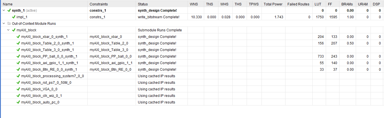
A picture below shows how many resources were used. You can find this information under Design runs below the block diagram.
The game algorithm is all written in c programming language, and it is running separately from the FPGA part. I think the best way to explain the code is if I describe each function with a few sentences.
/*PING PONG game function short explanation*/

void initialization(){
    /*
     * Pointers are set to memory space.
     */
}

void StartPositionBall(int background, int sizeXBall,int sizeYBall, int OffsetStartXBall, int OffsetStartYBall){
    /*
     * Start position for the ball
     * Determine how much array I am going to use
     * The background needs to the the same in all components, so it is set as global variable
     */
      /*
      * Another array for keeping score is       * set to zero.
      */

      /*
       * Set start value for the variables, that are later use for tracking position
       */
}

void StartPositionTables(int sizeXTable, int sizeYTable, int OffsetStartXTableOne, int OffsetStartYTableOne, int OffsetStartXTableTwo, int OffsetStartYTableTwo){
    /*
     * Set background, set the array size, and start position on the screen
     * Set start value for the variables, that are later use for tracking position
     */
}

void DrawFigures(int background){

    /*
     * Fill the array with data
     * positionAndEnable variable, position of data + enable bit
     */
}


void PositionTmpBall(int SpeedX){

    /*
     * Absolute position on the screen, and relative position according to the table
     * When it reaches the max positions, the direction is changed
     */

    /*
     * When you miss the ball the game is stoppend, until you don't press a button,
     * In the meantime function that tracks score is called, and the score bar is colored.
     * 2 seconds break before we continue with the game, because we don't want
     * table to moves because of the pressed button
     */
}

void PositionTmpTables(unsigned int buttonState){
    /* Similar to upper function, we track the tables position
     * we set maximal position on the screen
     * User changes directions with buttons
     */
}

unsigned int ReadButtons(){
    /* Save the button state  */
}

void ReStart(){
    /* Restart the game, put everything in the start position, polling the buttons, when the button is pressed start the game.
     * After two second we continue
     */
}

void circle(int position, int radius, void* data_in_pointer, int CircleColor)
{
    /* Draw ball  */
}

void KeepScore(int NumPlayer){
    /* Function for tracking score
     * Depending on which player got the point we call the function
     * every time the Player_variable is increased by 10.
     * When one or another player gets to 11 points, he/she won and the array is cleared
     */
}
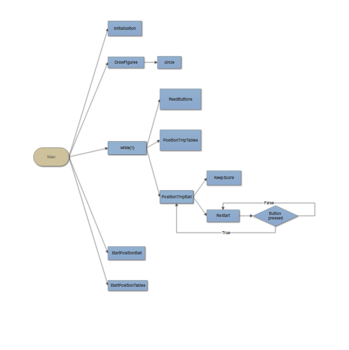
For easier ilustration of program execution below is a flow chart that shows how functions are called.
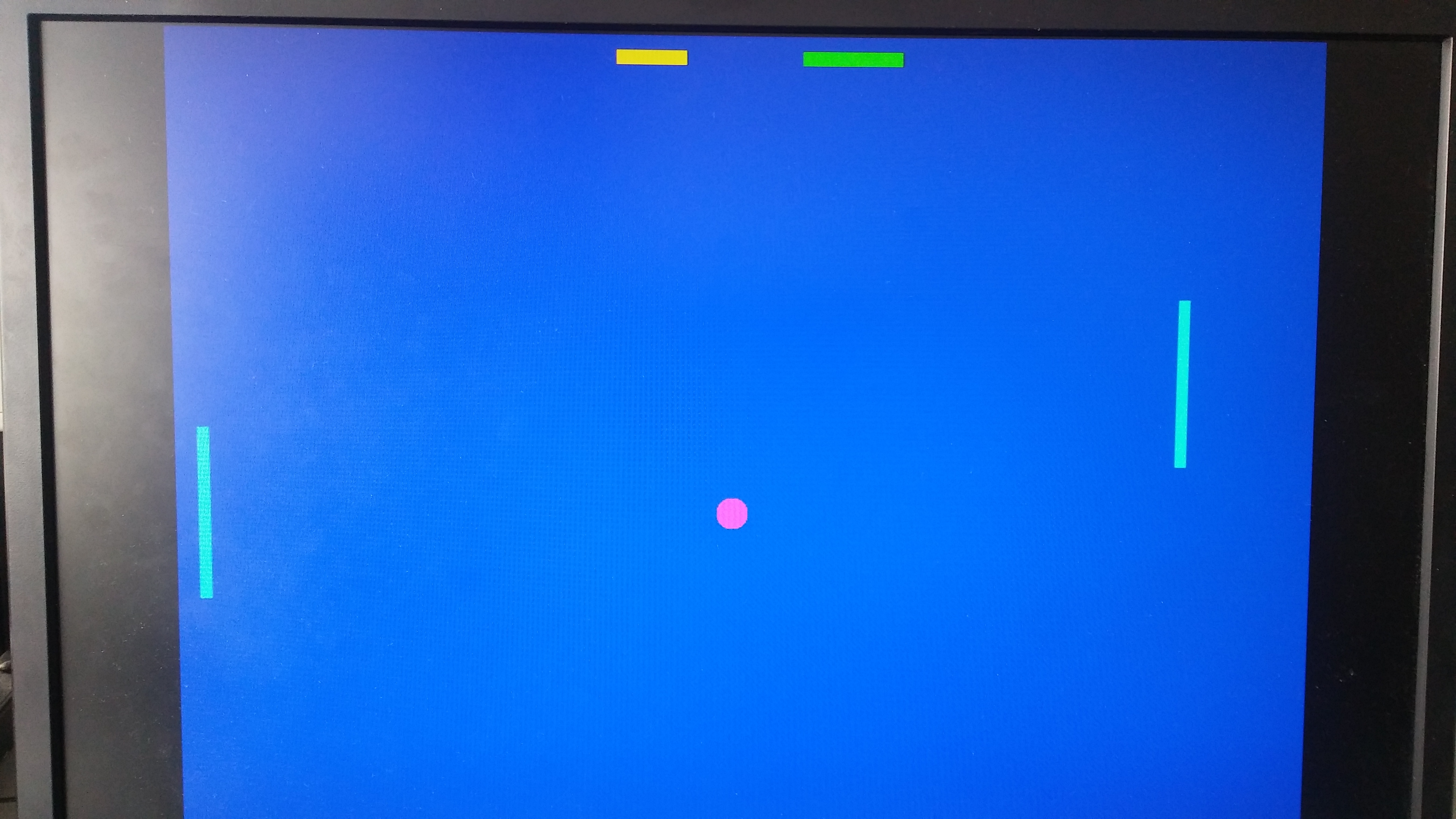
Below is the picture how the games looks on the monitor.
In conclusion, this was my first project on Red Pitaya board. In the beggining I had quite a few problems, before everything was working the way I wanted, and even though I am quite happy with the result there are a few things that could be added and improved. Less resources could be used if all the arrays would be declared in one component and all the data bus width would be used. It depends what your goal is, less components spare the number of resources, but everything becomes more complicated to follow. Additional colors would also make aplication more interesting for different kinds of implementation.
Another interesting thing would be to add bloks that display more graphic forms, for example different figures, text and graphs, that would really contribute to the application usefullness.